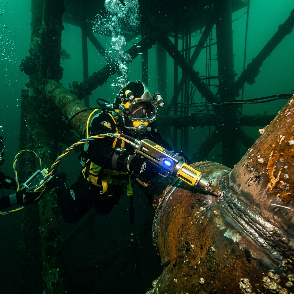
Alternating Current Field Measurement (ACFM)
Method Overview
Electromagnetic technique for detecting and sizing surface-breaking cracks in conductive welds, even through thick coatings.
Core Method Specifications
Target Applications & Governing Standards
1 Scopes ConfiguredMethod Limitations & Operational Boundary Conditions
Critical physics limits, thermal envelopes, blind spots, and ASME Sec V / API procedural boundaries for ACFM.
Probe coil balance drift must be re-zeroed in air when inspecting hot surfaces.
Zero dead zone at surface; can size cracks starting directly at plate face
None (dry electromagnetic field induction)
Induced uniform current lines must run perpendicular to the crack length. Transverse cracks require 90° probe rotation scan
- •Sub-surface discontinuities with no surface-breaking component (blind to embedded slag or lack of root penetration)
- •Ferrous plate edges or sharp 90° step shoulders cause magnetic field compression that masks small cracks
Abrupt lift-off transitions when dragging probe across high weld crowns creating false Bx butterfly loops
Volumetric depth confirmation and root flaw detection
Rapid visible verification of crack ends when paint removal is acceptable
Technique-to-OEM Compatibility Matrix
Verified manufacturers, instrument models, and diagnostic portals supporting ACFM.
Eddyfi Technologies
Advanced non-destructive testing conglomerate encompassing Eddyfi electromagnetic arrays, Silverwing tank floor scanners, Teletest guided waves, Inuktun robotic crawlers, and M2M phased array instruments.
TSC Subsea
Specialist offshore manufacturer of Alternating Current Field Measurement (ACFM) crack detection instruments and ROV-deployable scanners for subsea jackets and risers.