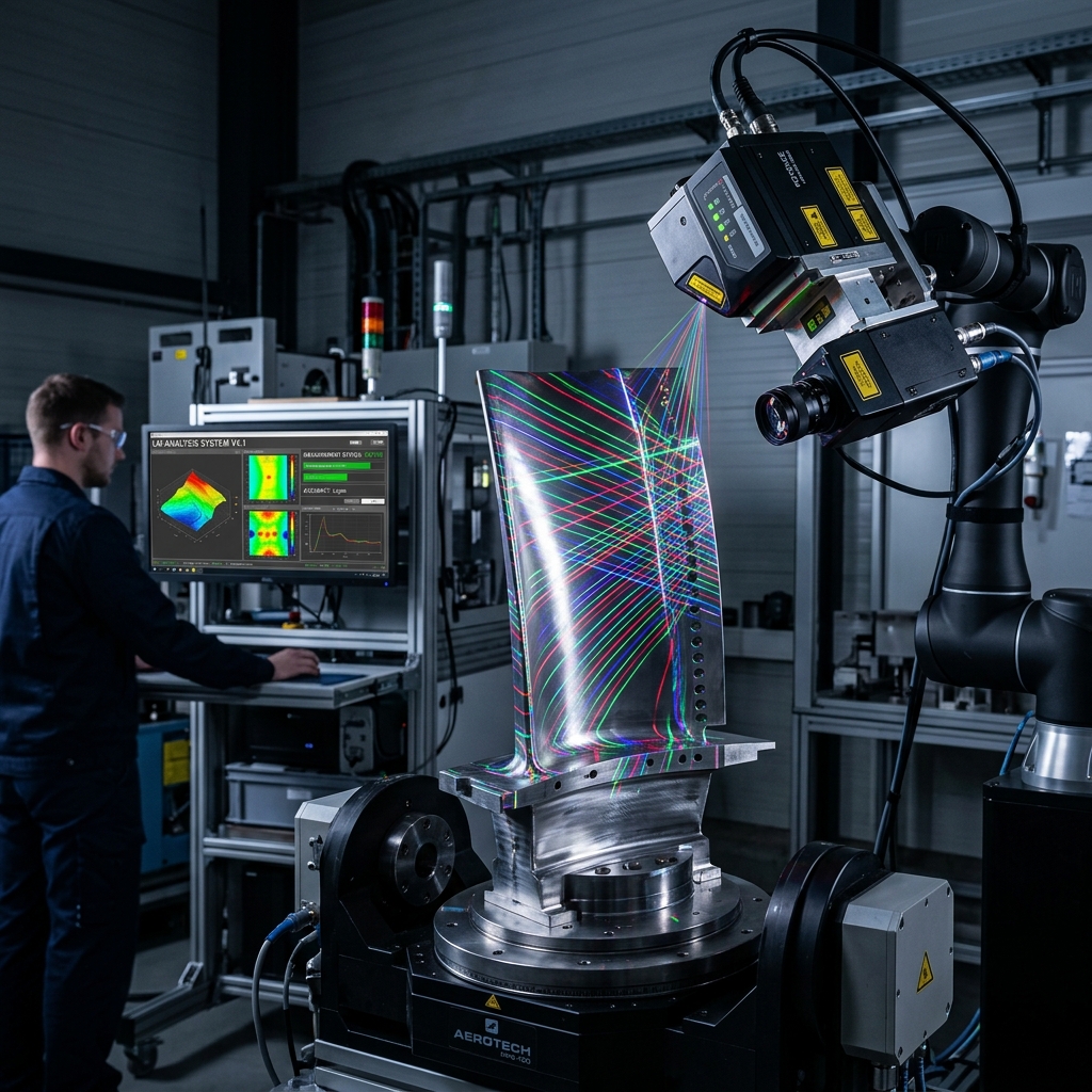
Laser Testing Methods (LM)
Method Overview
High-precision surface profiling, shearography, and holography using laser alignment systems to detect micro-deformations.
Core Method Specifications
Target Applications & Governing Standards
1 Scopes ConfiguredMethod Limitations & Operational Boundary Conditions
Critical physics limits, thermal envelopes, blind spots, and ASME Sec V / API procedural boundaries for LM.
Air turbulence and ambient temperature gradients refract laser beams, creating fringe drift in shearography systems.
Optimized for near-surface skin-to-core disbonds and interlaminar delaminations
None
Interferometer must look directly at surface deformation under vacuum or thermal excitation
- •Deep volumetric voids in thick monolithic metallic structures (method detects surface displacement strain gradients)
- •Structural areas subjected to external mechanical vibration during laser exposure
Localized thermal expansion differences near metal fasteners mistaken for delaminations
High-frequency immersion or air-coupled UT to confirm depth and ply number of delaminations
Flash thermography for rapid wide-area composite skin disbond screening
Technique-to-OEM Compatibility Matrix
Verified manufacturers, instrument models, and diagnostic portals supporting LM.
Dantec Dynamics
Pioneer of laser shearography, digital image correlation (DIC), and optical measurement systems for composite aerospace structures and wind turbine blade testing.
Micro-Epsilon
OEM Manufacturer for LM inspection systems.
Keyence
OEM Manufacturer for LM inspection systems.
FARO Technologies
OEM Manufacturer for LM inspection systems.