Computed Radiography (CR)
Method Overview
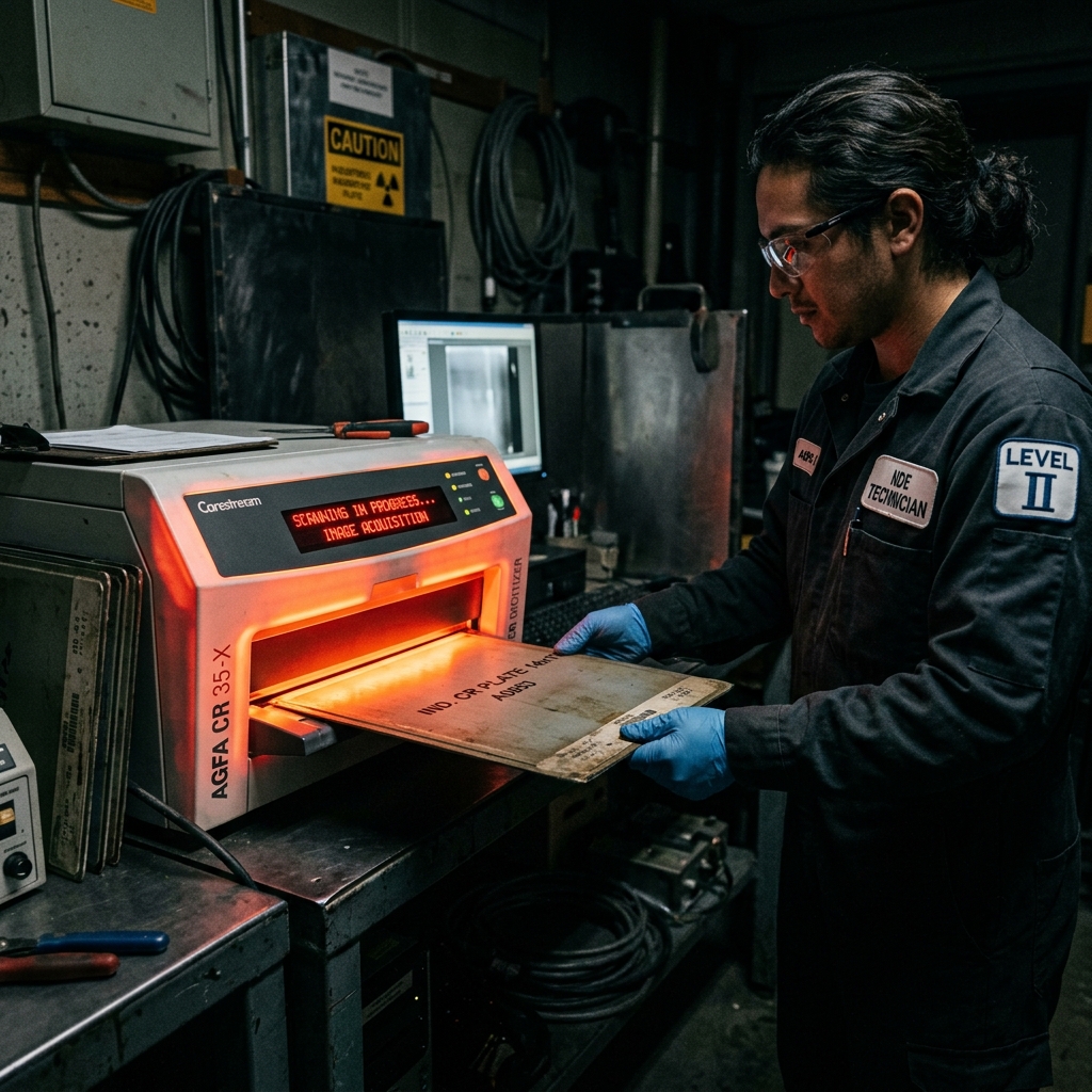
Filmless radiography utilizing photostimulable phosphor imaging plates to capture and digitize internal component geometry.
Core Method Specifications
Target Applications & Governing Standards
1 Scopes ConfiguredMethod Limitations & Operational Boundary Conditions
Critical physics limits, thermal envelopes, blind spots, and ASME Sec V / API procedural boundaries for CR.
Latent image fading occurs rapidly on imaging plates if exposed to heat (> 40°C) or prolonged ambient light.
Zero physical dead zone
Planar flaws must align within ±5° of radiation beam axis for acceptable contrast threshold
- •Tight planar lack of sidewall fusion oriented off-axis from beam vector
- •Laser scanner optical artifacts (laser jitter, scan line dropout) mimicking linear discontinuities
Scratches, dust particles, and cracked protective laminate on reusable phosphor plates
Comprehensive weld inspection to verify planar bevel fusion and determine through-wall depth
Direct thickness verification on areas showing radiographic density loss
Technique-to-OEM Compatibility Matrix
Verified manufacturers, instrument models, and diagnostic portals supporting CR.
Waygate Technologies
Global industrial inspection conglomerate under Baker Hughes, encompassing Krautkrämer ultrasonic, Seifert radiography, Everest borescopes, and phoenix|x-ray computed tomography.
Carestream NDT
Global benchmark for digital radiography systems, computed radiography (CR) phosphor imaging plates, and high-contrast industrial NDT films (formerly Kodak NDT).
Dürr NDT
German pioneer of computed radiography (CR) laser scanners, high-resolution digital detector arrays (DR flat panels), and D-Tect X radiographic evaluation software.
GE HealthCare
Global enterprise medical imaging innovator manufacturing clinical Micro-CT systems, high-frequency ultrasonic diagnostic transducers, and hospital radiological assemblies.
KUBTEC
OEM Manufacturer for CR inspection systems.